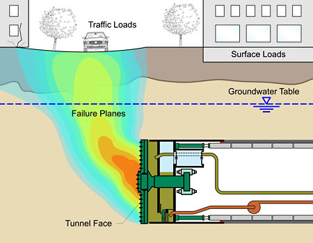
 1. Failure mechanism at tunnel face  Figure 2a: Result of insufficient face support pressure Face Support Pressure and Its Importance During tunnel construction, soil is removed from the tunnel face. The soil layer in front and above the tunnel face exerts active earth pressure. The presence of infrastructures or surcharge also contributes as additional earth pressure. For the tunnel alignment below the groundwater table, water pressure is the another significant component of pressure acting at the tunnel face. This phenomenon is illustrated in Figure 1. For stability, the layers of soil at the tunnel face should have sufficient strength to balance these forces. In many projects, tunnels will encounter several layers of loose soil or weathered rock. The face may not be strong enough to bear such pressures or may be unstable. Therefore, the soil mass in front of the cutterhead can collapse which would then result in excessive settlement at the surface. Examples of such incidences are presented in Figures 2a and 2b. Support pressure needs to be built up at the face of tunnel, to counterbalance the pressure generated by the soil, water and overlying infrastructures. This pressure is known as support pressure. Sometimes, even with stable geology, face support pressure needs to be built up in order to prevent the inflow of water into the tunnel. A decrease in the groundwater level may result in consolidation and thereby surface settlement. In cases of mechanised tunnelling, support mediums will be used to build the required face support pressure. Common support mediums used are bentonite slurry, earth paste, and compressed air. Choosing a support medium depends on various factors, a few of which are properties of soil and the type of TBM used. There are some adverse effects to applying excessive support pressure as it may lead to surface heave and ground distortion. Inadequate support pressure may cause ground settlement. Therefore, an adequate range of face support pressure is needed to stabilize the face, which in turn will minimize settlement, avoid ground collapse, prevent ground heaving and allow for reliable advance of the TBM.
It also allows for safe hyperbaric interventions for cutterhead inspection and maintenance.
 Figure 2b: an other result
Method of Application of Face Support Pressure The geological conditions of the project mainly govern the method of application of support pressure. The type of the TBM used depends mainly on the choice of the support medium.
 Figure 3: Slurry TBM 1. Slurryschild
If using a TBM with a slurry shield (also called Hydro Shield) the support of the face is accomplished by pressurized slurry, which in most cases is a bentonite suspension (a mixture of special clay and water). The excavation chamber is filled with slurry which supplies support pressure as well as serves as a medium to transport the excavated soil out of the tunnel. By using the slurry shield technology, support pressure is directly controlled by regulating the inflow and outflow of the suspension. Yet when using mixed shield technology, it is controlled by using compressed air.
The transfer of applied support pressure relies on the rheology of the slurry. The slurry has to be adopted according to the soil parameters and must be observed and documented frequently.  Figure 4: EPB TBM 2. Earth Pressure Balance (EPB) Schild
If using a TBM with an Earth Pressure Balance (EPB) Shield, the tunnel face is supported with an earth paste formed by the excavated soil. For better conditioning of the soil, water and some additive (i.e. foam) are mixed with the excavated soil in the cutter head. This technique improves soil consistency and workability thereby reducing the required cutterhead torque. In "closed mode operation" the working chamber is completely filled with conditioned excavated material, the earth paste. The support pressure is transmitted to the soil by pressurising the earth paste through the thrust force transfer into the bulkhead. The pressure level is controlled by the inflow of excavated soil due to the forward movement of the TBM in relation to the outflow of soil from the discharging screw conveyor. It is measured by the readings of the earth pressure sensors at the bulkhead. 3. Compressed Air
The tunnel face can be supported by compressed air. In mechanized tunneling, it is mainly adopted during inspection and maintenance of the cutter head. During this time, the level of support medium is dropped down and the missing volume is replaced with compressed air. Once the required drawdown level has been reached, the tunnel face becomes open for inspection.
Calculation of Face Support Pressure For the calculation of the face support pressure, the following factors have to be considered.  Figure 5: Elements of face support pressure Selection of suitable cross-section
Depth of tunnel
Diameter of tunnel
Groundwater level
Supporting medium
Active earth pressure
Safety concept and tolerances
Operating modes 1. Selection of the Suitable Section
A careful selected cross-section representing typical characteristics of the majority of the alignment will be an economical way of getting information on face support pressure. Following factors should be considered by the selection of cross sections: High groundwater level will have a large impact on the tunnel face support pressure. Sections with heavy surface loads or with soil layers having poor shear strength may generate larger earth pressure. On the other hand, sections with relative small cover will be critical for the blow out safety.  Figure 6 2. Depth and Diameter of Tunnel
With the increase in depth, pressure due to groundwater increases linearly. The variation in earth pressure depends on the soil parameters and the chosen model. With the increase in diameter of the tunnel, the area of the tunnel face being supported will also increase by a quadratic function. This, of course, results in larger face support pressure. 3. Water Pressure
When calculating face support pressure, hydrostatic water pressure is used in the face support pressure calculation. If there are multiple groundwater levels or if there is a significant fluctuation in the water level, as in the case of a tide, the appropriate level has to be supplied.
Water pressure = unit weight of water x head of water at the point of calculation 4. Support Medium
As mentioned in Section 2, the support medium will depend on the type of Tunnel Boring Machine (TBM) being used as well as its operating mode, advance mode or drawdown. Slurry shields use pressurized slurry, mainly bentonite suspension, whereas an EPB shield uses earth paste. The difference in their unit weight and operational tolerance has to be incorporated into the calculation of face support pressure. When compressed air is being used as a support medium, the difference in its pressure distribution diagram in comparison to the pressure distribution diagram of slurry or earth paste, as shown in Figure 9, will be relevant in the calculation  Figure 10a:
Schematic diagram of earth, water and support pressure in different mode a. Loads, b. TBM,
c. Advance mode, d. 1/3 Drawdown,
e. ½ Drawdown, f. 1/1 Drawdown 5. Active Earth Pressure
To determine the required active earth pressure at the tunnel face, information about the stratification of soil layers in the section, loads on the surface and head of groundwater will be necessary. The weights of permanent structures like buildings, dams, dykes, fills, etc. above the section are considered constant loads. Loads of vehicles like cranes, trucks, etc. will be considered temporary loads. Both of these loads will increase soil pressure, but only the constant load contributes against blow out and ground heaving. Geological conditions are key factors governing the construction of a tunnel. In addition to the grain size distribution, the soil stratification and the strength parameter of each layer will be important to determine the face support pressure. The shear strength of the material governs the stability of the face. In clay, it is the undrained cohesion cu. In sand and gravel, the angle of friction as well as drained cohesion c' are of interest. Each soil layer is different in its loading parameters. Such differences may be unit weight, thickness of the layer and the strength parameters, like angle of friction and cohesion. Active earth pressure is calculated using the two well-established models, Anagnostou & Kovári and DIN 4085: The basic difference between those methods is in the way of incorporating the effect of overlying soil layers. In the first model, strength parameters of soil are taken into consideration for the silo effect. The second model takes the depth of the tunnel, regardless of the soil types present above the tunnel, to calculate the reduction factor of the two-dimensional earth pressure. The model of Anagnostou & Kovári is more suitable as the support pressure calculated is more precise than with the model of DIN 4085.  Figure 10b: Schematic diagram 6. A. Anagnostou & Kovári Model
This model is based on the failure mechanism developed by HORN which consists of a wedge and an overlying right-angled prism as shown in Figure 6. The model was further improved by Anagnostou & Kovári in the 1990s adopting the silo theory of JANSSEN and TERZAGHI. According to the silo theory, the effective vertical stress acting at the tunnel acts is reduced due to the shear stresses along the sliding surfaces of the prism. This reduced vertical stress at the top of the wedge. The soil layer lying above the tunnel has an important role in the distribution of vertical pressure. The stability of the face is determined by equilibrium of the total forces acting on the wedge. Therefore, the support force (S) must equalize the resulting forces of the wedge itself and the weight from the prism reduced by the active resistances along the sliding surfaces, both sides and back surface of wedge.  Figure 7: Model of Horn 6. B. DIN Modell
In this model, three-dimensional active earth pressure is calculated according to DIN 4085, which is based on the failure mechanism theory of Piaskowski & Kowalewski, as shown in Figure 7. The method divides the tunnel face into multiple horizontal strips. The three-dimensional active earth pressure acting on each strip is calculated with the two-dimensional active earth pressure method, adjusted by reduction factors. These factors are calculated depending upon the ratio of depth of the layer to tunnel diameter. 7. Safety Concept and Tolerances
A. Partial Safety Factor
To ensure stability of the tunnel face, it is necessary to counterbalance the total force of active earth and water pressure. These forces are multiplied separately with safety factors as per the concept of partial factor of safety. Necessary support force = η a E a + η w W Where, η a and η w are partial factors of safety for active earth pressure (Ea) and water pressure (W) respectively.
B. Ordinate Check
To prevent the lack of equilibrium in selected local areas, critical nodes have to be checked individually. Such nodes may be the crown, invert or draw-down points of the tunnel in which the applied support pressure should at least be more than the local water pressure plus 10 kN/m². The safety factor for ground heaving and blow out must be reached, as well. These checks are known as ordinate checks. Figure 8 shows an example of an ordinate check for 1/3 drawdown where the applied support pressure is less than the earth and water pressure at 1/3 drawdown point.  Figure 8: Model of Piaskowski & Kowalewski C. Operational Tolerance
When using hydro-shield technology, the support pressure is directly controlled by the inflow and outflow of suspension. Yet in slurry shield technology, it is controlled using compressed air. Certain tolerances will be necessary to compensate the fluctuation of the face support pressure in the working chamber. This tolerance is known as operational tolerance and is about 0.1 bar.
In the case of an EPB shield, the face support is regulated by the inflow of the excavated soil due to the forward movement of the TBM in relation to the discharge of the screw conveyor. The normal operational tolerance adopted for an EPB shield is 0.3 bars. 8. Operating Modes
While the TBM is in excavation mode the working chamber is filled with the support medium. To facilitate the entry of personnel, as well as expose the tunnel face and the top of the cutter head, the level of support medium can be reduced. During this time, support pressure will be maintained by exchanging the missing volume with compressed air.
The pressure diagram of compressed air is different to that of the normal support medium as shown in Figure 9. The operational tolerance will also be different from the one in advance mode. During excavation mode the mixed excavated soil increases the unit weight of the slurry. Prior to the hyperbaric interventions the slurry is replaced with the fresh suspension which has a lower unit weight. This will cause a difference in support pressure between drawdown and advance mode of TBM operation. The most common modes to be analysed are:  Figure 9: Example of Ordinate Check 9. Advance mode
The excavation mode in which the working chamber is filled with supporting medium mixed with excavated soil.
1/3 Drawdown
The level of support medium will be lowered to the depth equal to one third (1/3)
of the tunnel diameter from the crown.
It is not applicable when the depth of drawdown is smaller than 2 m.
1/2 Drawdown
The level of support medium will be lowered to the tunnel axis.
1/1 Drawdown
The level of support medium will be lowered to the tunnel invert.
Check for Blow Out Safety In a tunnel with relatively low cover, the applied support pressure may lead to ground braking during advance mode, and blow out of applied compressed air during drawdowns. Consequently, the sudden loss of support pressure takes place. To prevent these phenomenons, the ratio of weight of overburden soil and water to the applied support pressure should not be smaller than the predefined safety factor.
This is an additional safety check that should be performed for each face support pressure.  Figure 11: Blow out |